You are here: > Home > Release > Steel Tube Electrohydraulic Umbilical
Steel Tube Electrohydraulic Umbilical
|
|
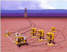
The subsea field in the image (top left) is a small shallow water development consisting of:
- Three wells
- A manifold with a pigging loop
- Jumpers from the wells to the manifold (ROV-installed)
- Dual pipelines terminating in pipeline end termination skids (PLETs)
- Jumpers from the PLETs to the manifold
- An umbilical terminating in an umbilical termination assembly (UTA)
- Electrical and hydraulic flying leads from the UTA to each subsea well
The platform to which all this ties back is a bottom founded jacket-and-pile structure. The umbilical is therefore pulled from the sea bottom to the deck through a tube, or is otherwise supported throughout its entire ascent. It is a static umbilical.
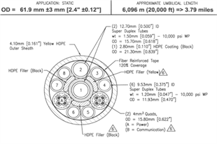
Because it is static, and because the field is relatively small, a simple umbilical like the one depicted in the image (above right) would work.
A simple electrohydraulic (EH) umbilical will have the following components:
- Steel tubes to deliver chemicals and hydraulic power to the subsea production system. There may be one or more backup tubes for use in case of tube failure. Tubes may be sheathed in LDPE to achieve the proper cross-sectional geometry.
- One or more electric cables (usually quads of 4 to 10 square mm)to deliver power and multiplexed signal to the subsea control system, and to carry instrumentation signals back to the surface control station.
- Fillers to help create the proper cross-sectional geometry.
- Tape which is wrapped around the elements as they are bundled and twisted into an umbilical. This holds the entire assembly together until it is passed through the extrusion head to receive its HDPE sheathe.
- HDPE Sheathe